How Does A Dual LED Blown Fuse Indicator Work?
Question:
- Can you use a 3 pole L9 breaker on a 1 or 2 pole load?
- Can you use a 3 pole L8 breaker on a 1 or 2 pole load?
- Can I use just 2 of 3 poles from L9-10/3/C (2 phases from 3phase lines) 1st and second pole?
Answer:
You can use a 3 pole device on a 1 or 2 pole load or a 2 pole device on a 1 pole load but the following should be noted:
- This will not affect the short circuit tripping functionality of the device.
- This will affect the thermal calibration of the device. The device is calibrated with power on all of the available poles. Not having all the poles powered will result in less heat in the breaker. This lower heat level will result in the pole(s) being used to allow for higher current levels (more heat) before thermally tripping
- A 3 pole device will not have the DC ratings that many of the 1 or 2 pole devices may have. If the 1 or 2 pole version of the 3 pole device is rated for DC, the poles in the 3-phase device can be used on the same voltage DC loads, but will not be labeled with any DC voltages.
Question:
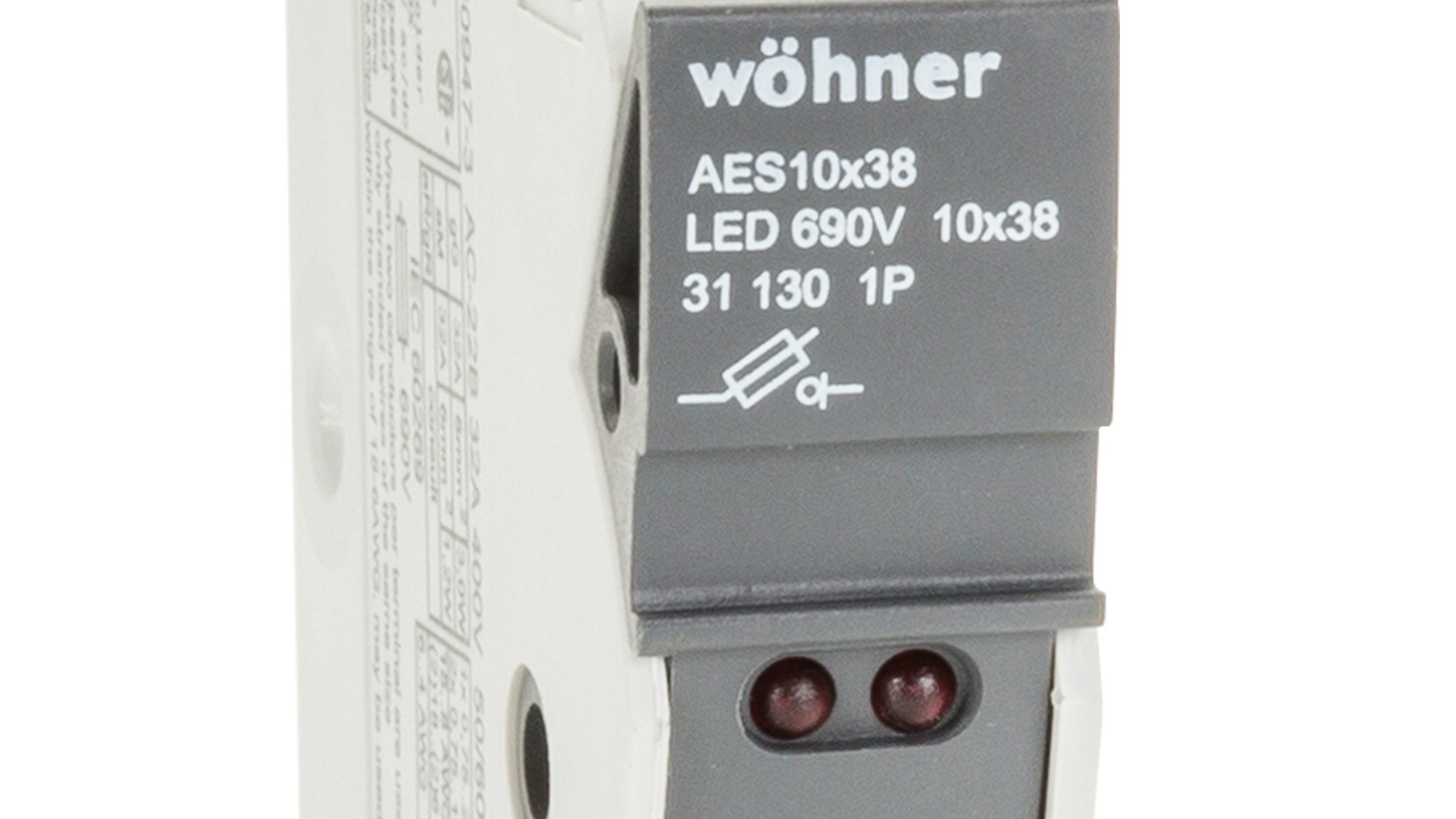
How does the dual LED blown fuse indicator work on fuse holders and terminals?
Answer:
Indicators on fuse holders and terminals form a parallel path with the fuse they are monitoring. The indicator consists of a contact assembly (making contact with the fuse at both the line and load side), a high value resistor, and the indicator (see diagram A).
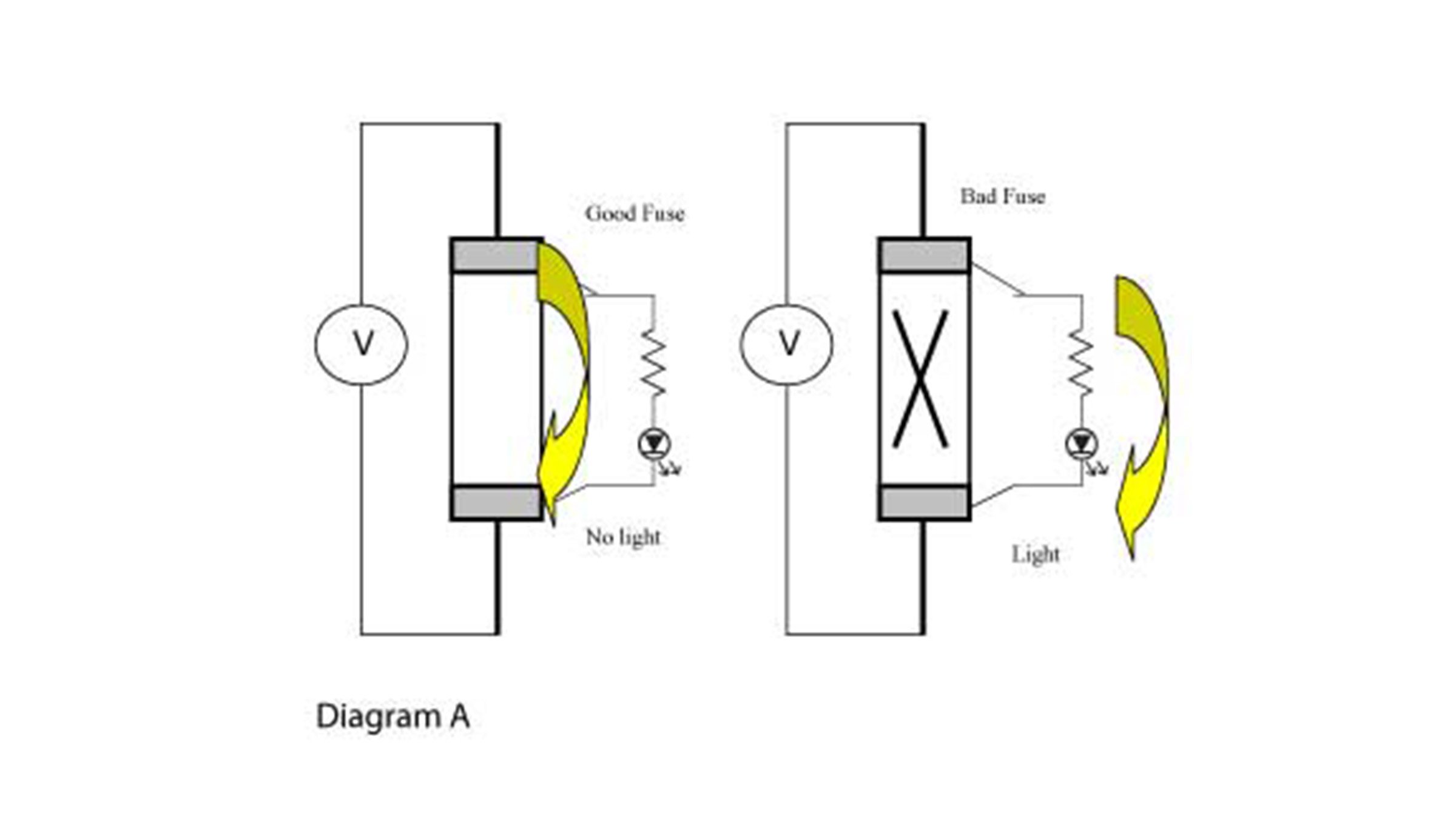
When the fuse (and fuse holder) is energized, and when the fuse is conducting, the electrical path through the fuse has a significantly lower resistance than the path through the indicator, resulting in substantially all of the current passing through the fuse. When the fuse (and fuse holder) is energized, and when the fuse is open, then the electrical path through the indicator is the only electrical path. Current flows through that path and the indicator illuminates.
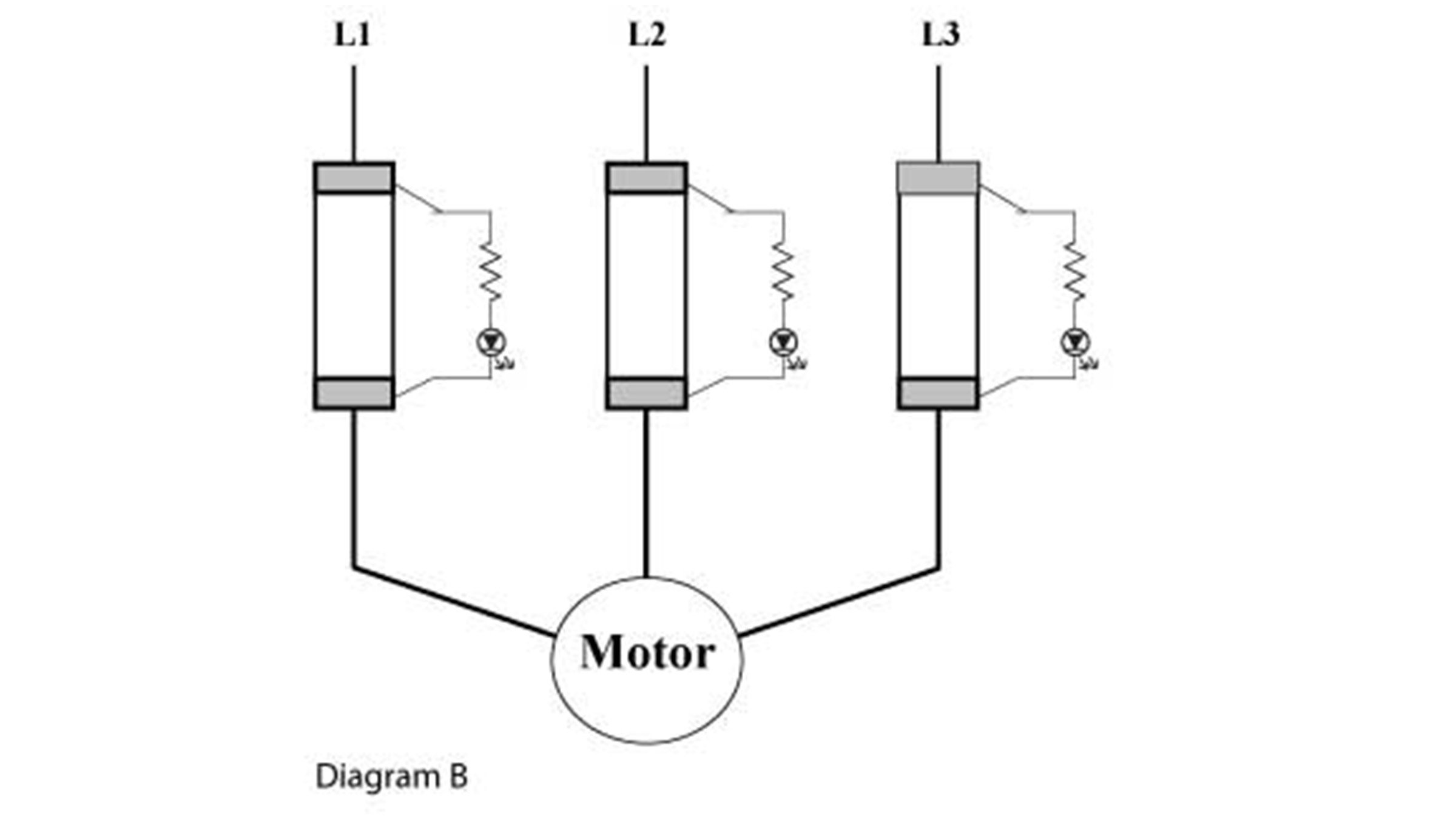
When Used In An Electrical Circuit, The Application May Look Like Diagram B.
When power is applied (L1, L2, and L3), if any fuse becomes open, the associated indicator illuminates. In addition, if a phase is present, but no fuse is in place, the associated indicator will not illuminate. The ferrules of the fuse complete the indicator circuit, so no fuse -> no ferrule -> no circuit -> no light.
Note: If a phase is not present, then the associated indicator would not illuminate, no matter what the status of the fuse.
For DC Circuits: One LED light lit indicates a blown fuse on a DC application. Since DC has a polarity of "+" or "-", only one bulb senses 1/2 of the sine wave for the given DC circuit. The light being lit depends on how the plus and minus are wired.
For AC Circuits: Two LED lights lit indicate a blown fuse on an AC application. Since AC is sinusoidal, the LED senses 1/2 of the sine wave and the other 1/2 causing both lights to be lit for a given AC circuit.
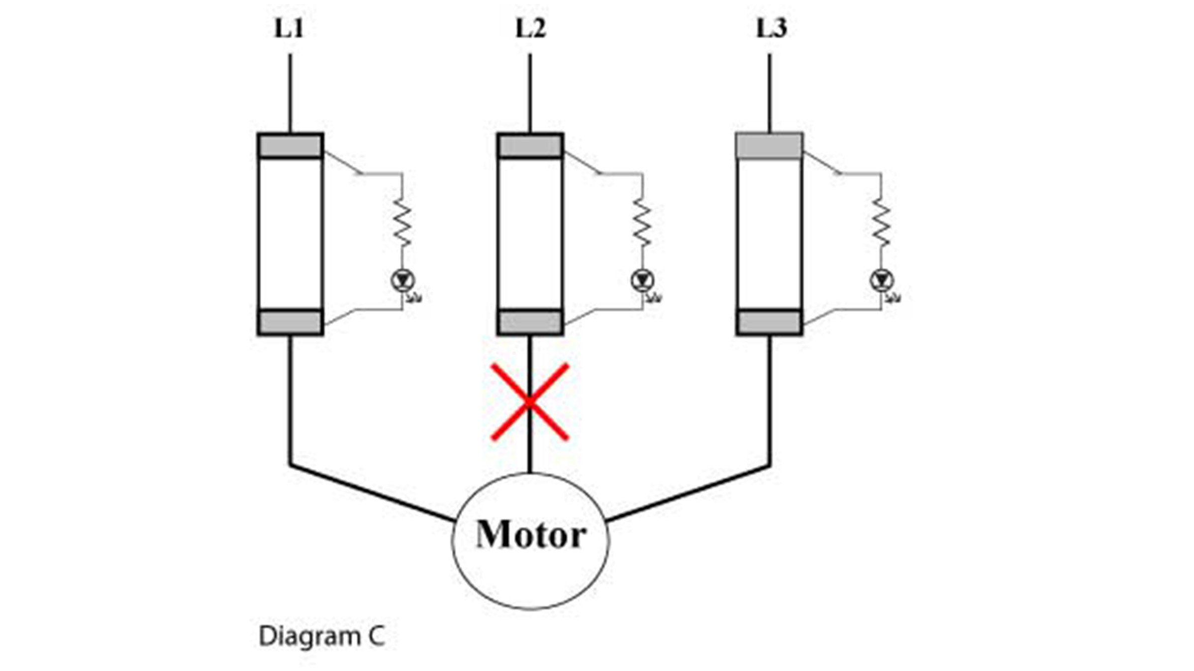
If There Should Be A Wire Break To The Motor See Diagram C.
When power is applied (L1, L2, and L3), if the fuse in the L2 phase becomes open, the associated indicator will not illuminate since there is not a complete electrical path. Indicators in the L1 and L3 phase would work if the fuse in L1 or L3 subsequently opened.
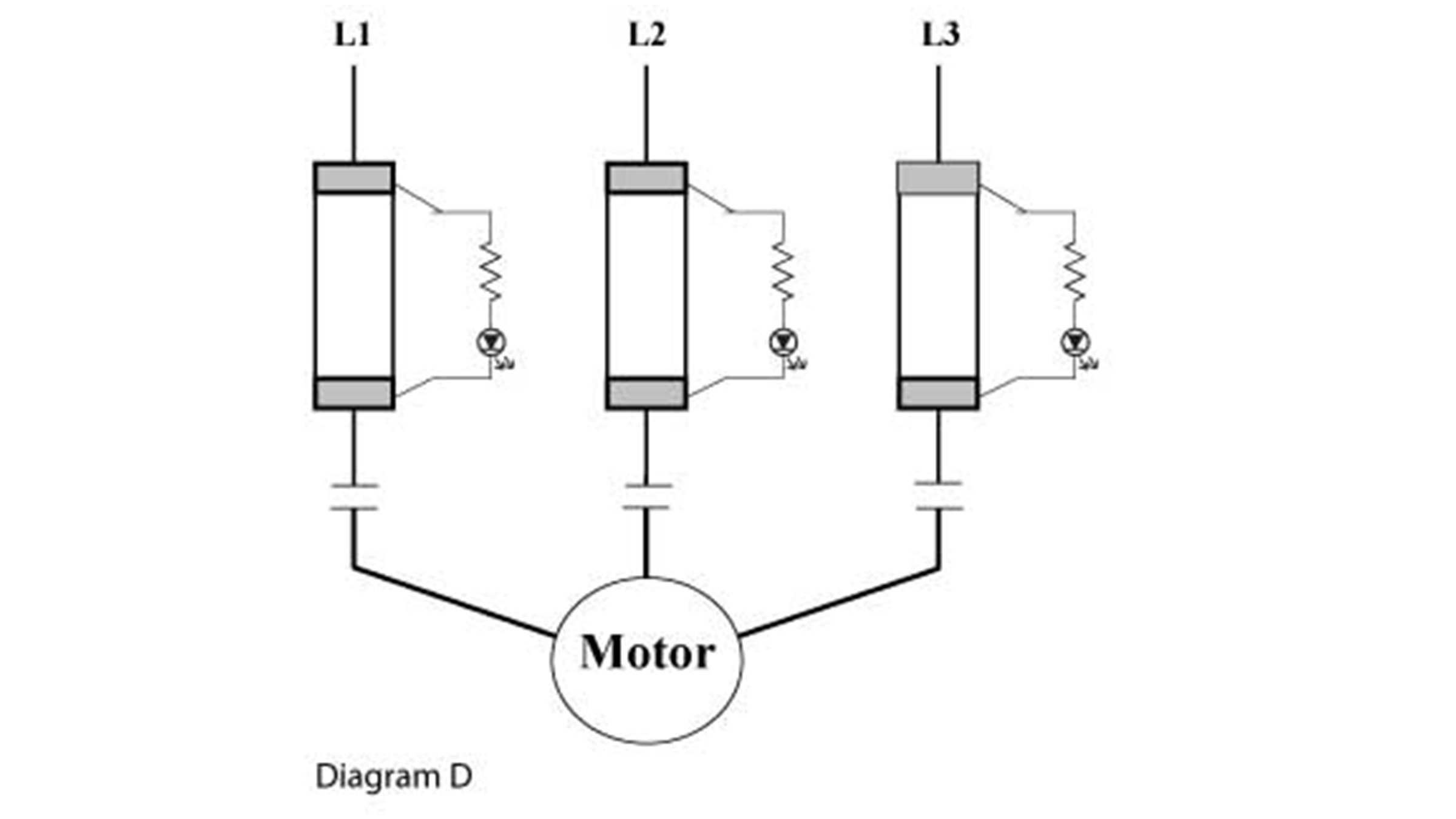
If The Fuse Holders Are Used With A Contactor (Motor Starter) See Diagram D.
When power is applied (L1, L2, and L3), and if the contactor is energized, if a fuse becomes open, the associated indicator will illuminate. However, if the contactor is open, then no indicator will illuminate since there is not a complete electrical path.
For additional information please contact your nearest authorized distributor, sales representative, or call our customer service or technical support lines.
Related Links